(Page 3)
The voltage/current (voice coil impedance) and three acceleration/current frequency response functions (FRF) of Figure 6 illustrate typical responses of the model of Figure 4. Note the two sharp resonance spikes. These essentially mark the Frequency Range over which the shaker may be used. The lower frequency spike (here at ≈7 Hz) is the Suspension Resonance while the upper one (≈5 kHz) is the Armature Resonance. The 7 Hz suspension resonance is clearly reflected in the coil impedance; the 5 k Hz armature resonance reflects too, but less clearly. The Isolation Resonance is less clearly seen. It produces the slight “kink” evident (between 2 and 3 Hz ) in the in the three acceleration/current FRFs. The isolation mode does not reflect into the coil impedance because this mode’s shape has no relative motion between the coil and the shaker body.

Figure 6: Solution FRFs show voice coil voltage and mass accelerations per ampere of drive current.
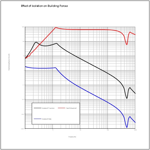
Figure 7: Reducing floor vibration by isolating the shaker.
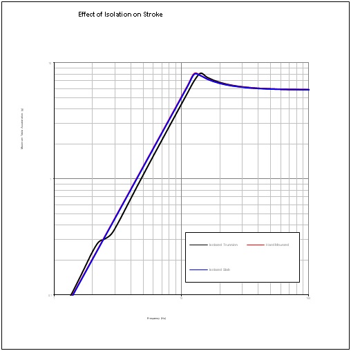
Figure 8: Comparison of maximum acceleration shakes with different isolation configurations.
Isolation of the shaker is absolutely required to keep the machine from unduly shaking the building that houses it. Standard configuration Sentek Dynamic shakers provide air spring isolators at the trunnion mount or under the feet of a monobase supporting a shaker and slip table. These soft air springs support the shaker body and minimize vibratory forces passed to the laboratory floor. Figure 7 illustrates how successful isolation is. Here, maximum possible acceleration sweeps using the same payload are compared. The tests differ only in the isolation configuration used. The black trace (trunnion isolation) shows an order-of-magnitude reduction in floor reaction forces over a rigidly mounted shaker (red trace). The blue trace illustrates the further reduction of building forces possible by mounting the shaker (rigidly) to a large reaction slab and isolating that slab from the building foundation. This, of course, is a far more expensive solution.
However, vibration isolation is not without cost. Figure 8 shows the table acceleration achieved in these three tests. (Note the hard-mounted and slab isolated traces are virtually indistinguishable.) The trunnion isolated test shows a reduction in the maximum possible DUT acceleration from the isolation resonance frequency to the suspension resonance frequency. This reduction occurs because part of the shaker’s stroke is expended to accelerate the shaker body away from the armature.

Clearly, the Continuous Displacement and Shock Displacement can never exceed the shakers peak-to-peak Stroke. In examining the feasibility of running a particular test, these displacement parameters should never exceed the De-rated Stroke of the shaker. Now let’s look at the other limiting parameters.
The system’s Maximum Velocity specification is actually a reflection of the amplifier’s maximum voltage. Recall (from Figure 4) that a back EMF voltage is generated by the voice coil in proportion to its velocity relative to the shaker body. If this generated voltage should exceed the maximum voltage the amplifier can provide, the system cannot maintain control of the armature’s motion. Hence the maximum velocity specification is a feedback control issue and not a structural limit. Assuring that the test does not exceed the system’s maximum velocity is normally not a significant concern for random tests – it is of some concern for low frequency sine sweeps and it is of paramount concern for shock tests.
The Maximum Acceleration (Sine Peak) is a structural concern. Exceeding this maximum peak acceleration can result in damage to components of the shaker. This peak acceleration is a reflection of the stress acting within the armature. It is always prudent to resist over accelerating the armature transiently or continuously.
In like manner, the three force ratings (Sine Force Peak, Random Force RMS and Shock Force Peak) are “do not exceed” levels for the selected test system. They are measured in accordance with ISO 5344 which specifies the payload, random test spectrum and endurance durations. The force ratings are actually reflected levels of the maximum RMS current that may be applied to the voice coil without thermally damaging it. When the shaker is tested at its maximum sine force or to its maximum random force, the RMS current flowing through the voice coil is essentially the same. Hence the voice coil experiences the same 12R thermal power for the duration of either continuous signal qualification. The peak shock force level may be considerably larger (2X to 3X) than the peak sine force because it only persists for a short duration. A higher level of transient current (reflecting a higher force) is tolerated by the armature’s voice coil.