Battery Testing with CAN bus
1. INTRODUCTION
Research into new-technology batteries has accelerated over the last decade with the promise of energy density being significantly improved. This research has led to more lithium-ion battery applications in aircraft, electric and hybrid vehicles (EVs and HEVs), 2 and 4-wheel light electric vehicles (LEVs) and personal items such as laptops and wearable devices. Controlled release of energy from these new-technology batteries provides useful electrical power. Uncontrolled release of the energy can result in hazardous situations such as smoke, fire, explosions, or any combination thereof.
Uncontrolled energy releases can be caused by damage from a wide-variety of physical/environmental conditions or events such as temperature, humidity, vibration and shock. These conditions, be they from normal operation or a vehicle crash, can cause damage to batteries with catastrophic results. In a worst-case scenario, the damage can result in a rapid temperature rise of hundreds of degrees leading to thermal runaway and a risk of fire and explosion. The problems caused by environmental conditions or physical events can be reduced or eliminated by proper physical design of the battery and related mechanical systems. However, compliance to an applicable recognized standard must be validated by testing before the battery or related electro-mechanical component can be considered safe for its intended use. Battery safety standards and regulations require testing in combined abusive environmental conditions found in actual battery applications. Battery standards for EV/HEV, 2 and 4-wheeled vehicles, laptops, and wearable devices, include, but are not limited to the following:
IEC 62660-2:2016 Secondary Lithium-ion Cells for the Propulsion of Electrical Road Vehicles Reliability and Abuse Testing
IEC 62113-2:2017 Secondary Cells and Batteries Containing Alkaline or other Non-Acid Electrolytes – Safety Requirements for Portable Sealed Secondary Cells, and for Batteries Made from Them, for Use in Portable Applications.
IEC 62660-3:2016 Secondary Lithium-ion Cells for the Propulsion of Electrical Road Vehicles – Safety Requirements
SAE J2464:2009 Electric and Hybrid Electric Vehicle Rechargeable Energy Storage System (RESS) Safety and Abuse Testing
UN38.3:2015 Recommendations on the Transport of Dangerous Goods – Manual of Tests and Criteria – Section 38.3 Lithium Batteries
BATSO 01 Manual for Evaluation of Energy Systems for Light Electric Vehicle (LEV) – Secondary Lithium Batteries
UL 2271 Batteries for Use in Light Electric Vehicle (LEV) Applications

Figure 1. Sentek Dynamics’ Vibration Testing System for Battery Testing

Figure 2. Sentek Dynamics’ Environmental Testing System for Battery Testing
In recognition of the detrimental effects of combinations of temperature, humidity, vibration and input electrical power on electrical and electro-mechanical components with regard to safety, integrity, and performance during ground and flight operations, MIL-STD-810H, has been released with Method 520.5 added to cover the testing of components in combined environments. Testing in combined environments may induce failures that would not be exhibited during individual environment testing. New to this test method is the addition of input electrical power as an environment; to include voltage/frequency variations, and transients (if applicable) which are inherent to the system. While it is virtually impossible to replicate the complex mix of environments which can be seen during transport, storage, operation, and maintenance, the intent is to apply representative combinations of stresses to the device under test to determine performance and capabilities.

Figure 3. MIL-STD-810H for Combined Environment Testing of Batteries
Sentek Dynamics, in concert with its sister company Crystal Instruments, provides turn-key solutions for combined mechanical, environmental, and thermal testing required by a wide-range of standards and specifications. Sentek Dynamics’ THV Series Environmental Test Systems with the Crystal Instruments’ Spider-101 Controller provide a turn-key solution for product development/certification and reliability improvement. The Crystal Instruments’ controller with IEEE Time Synchronization is the optimum solution for combined temperature, humidity and vibration testing of batteries, electrical and electro-mechanical components. It is the only controller with the following advantages:
One user interface for setting up run schedules for temperature, humidity, vibration, etc.
Fully networked allowing users to connect multiple hardware devices through Ethernet which allows one PC to control all devices at the same time
Ability to extract battery information through a CAN bus and take various actions including emergency shutdown*
Access and control with one software application
Data acquisition is accurately time-synchronized
One combined test report – If test reports are generated separately from several apps, the time clock and schedules will not be coordinated, unlike the integrated test report generated by Crystal Instruments’ EDM THV Software

Figure 4. Sentek Dynamics’ THV Series Chamber for Combined Temperature, Humidity and Vibration Testing
*The Controller Area Network bus or simply CAN bus protocol is a standard used to allow Electronic Control Units (ECUs) to communicate in an efficient manner with minimal wiring and without a central computer. Originally developed for automotive applications, it has gained wide acceptance in automotive and aerospace industries. The ability to acquire battery (and individual cell) information such as voltage, current, temperature, etc. during combined temperature, humidity and vibration testing and take predefined action(s) is a major advantage only available with the Crystal Instruments’ Spider-101 Controller. The intuitive design of the Spider-101 EDM software allows customers to tell from the Run Log when and why a test stopped, or action was taken. When CAN bus data received in Spider-101 EDM software is displayed and compared to data received in a dedicated device with CAN bus software the values are identical.
2. Equipment For CAN Bus Battery Testing

Figure 5. Comprehensive Battery Testing Application Setup Used in CABRI Facility
Sentek Dynamics Extra-High Force Electrodynamic Shaker
Vibration Controller: Crystal Instruments Spider-81 (OEM version)
Environmental Chamber
Charging and discharging equipment (Eg. Nebula NEEF45080060002-V001)
Battery Pack (DUT)
Integrated modules (CAN analyzer, serial port, network port, etc.)
2.1 Sentek Dynamics Extra-High Force Electrodynamic Shaker
Sentek Dynamics E-Series are water-cooled vibration testing systems designed for high-force, long-duration development and production testing of large automotive and aerospace components and assemblies. These extra-high force electrodynamic shakers provide cost-effective solutions to today’s demanding test requirements.

Figure 6. Sentek Dynamics E-Series Shakers
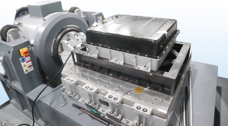
Figure 7. Sentek Dynamics E-Series Shaker Battery Testing System
2.1 Vibration Controller: Crystal Instruments Spider-81 (OEM Version)

Figure 8. Spider-81 Vibration Control System
Unlike traditional vibration test controllers that rely heavily on an external computer for real-time operation, the Spider-81 is the first vibration controller that directly integrates time-synchronized Ethernet connectivity with embedded DSP technology. This strategy greatly increases the control performance, system reliability and failure protection of the vibration test controller. It also allows a high channel count system to be configured without sacrificing performance.
Spider-81 vibration test controllers have voltage, charge, TEDS, and IEPE inputs which are ideal for shock, vibration and acoustic measurement or general-purpose voltage measurement. The internal flash memory stores test configuration data for controlling up to 64 channels simultaneously in addition to storing real-time analysis data. Multiple output channels provide various signal output waveforms that are synchronized with the input sampling rate. A bright LCD screen displays testing status information. Ten monitoring connections on each unit are used to read signals of analog inputs and outputs. Built-in isolated digital I/O and RS-485 serial ports enable interfacing with other hardware.
Ethernet connectivity allows the Spider-81 vibration test controller to be physically located far from the host computer. This distributed structure greatly reduces the noise and electrical interference in the system. One computer monitors and controls multiple controllers over the network. Since all the control processing and data recording are executed locally inside the controller, the network connection will not affect the control reliability.
The Spider-81 vibration test controller is built on IEEE 1588 time synchronization technology. Spider-81 vibration test controllers on the same network are synchronized within nanoseconds. With such unique technology and high-speed Ethernet data transfer, the distributed components on the network truly act as one integrated system.
2.1 Environmental Chamber
The Sentek Dynamic THV combined testing method, also known as The Department of Defense’s AGREE (Advisor Group on Reliability of Electronic Equipment) method of testing, combines three testing environments (temperature, humidity and vibration) in one chamber. The Spider controller by Crystal Instruments is standard with all THV Series environmental test chambers and is specifically designed for precise temperature and humidity control. The Spider controller precisely controls all aspects of a combined temperature, humidity and vibration test regime.

Figure 9. Sentek Dynamics THV Environmental Chamber
2.1 Charging and Discharging Equipment
The battery charging and discharging equipment allows the battery to cycle through real-world usage while undergoing the environmental stresses of the THV chamber.

Figure 10. Electrical charging and discharging device
2.5 Battery Pack (DUT)

Figure 11. Battery Pack
3. Customer CAN Bus Battery Testing Installation: CABRI
China Automotive Battery Research Institute Co., Ltd (hereafter abbr. as CABRI) originated from the leading initiation of China Association of Automobile Manufacturers (CAAM) and the General Research Institute for Nonferrous Metals (GRINM) with massive support from state and governmental departments, which serves as an industry & technology coordination and innovation platform, jointly established by domestic scientific research institutions, power battery manufacturers and automobile OEMs. The shareholders of CABRI include 11 enterprises of the General Research Institute for Nonferrous Metals (GRINM), China Ting New Power, FAW, Dongfeng, Chang’an, SAIC, Brilliance, GAC, CATL, and Tianjin Lishen while the registered total equity sums up to 850 million RMB (133 million USD).
CABRI is the center of the largest battery testing standards body in China and Sentek Dynamics shakers and slip tables, Spider controllers, and CAN bus control modules have been selected for use in battery testing research and development installations on site. This comprehensive setup enables vibration, stress, and strain testing, temperature and humidity control, and charging and discharging systems all controlled and monitored through a single interface in the EDM software via the CAN bus control module. http://www.glabat.com/class/view?id=54
The following figures show the CABRI installation for battery testing with CAN bus using Sentek Dynamics sourced components and software.
Figure 12. Vibration Controller
Figure 13. USB-CAN adapter
Figure 14. EDM software onsite at CABRI Facility
Figure 15. EDM Software User interface with battery CAN bus, charge and discharge, temperature and humidity, and vibration test control interface
The EDM software displays temperature and humidity, alarms, and running status. The software enables the user to manually execute program, fixed value, pause, continue, switch and other operations.
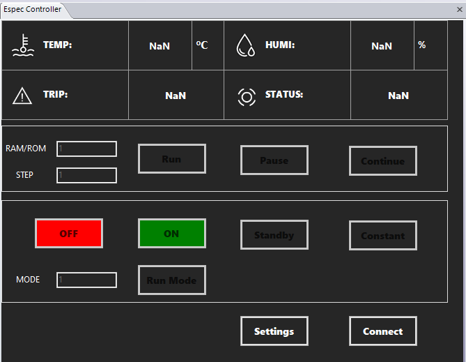
Figure 16. Environmental control interface implemented in EDM
The user can set basic communication information and linkage settings. Vibration Stop, Pause, Continue and other operations can be linked to the environment box.

Figure 17. Chamber control interface implemented in EDM
The user can set the charging and discharging settings to skip the steps to preform preparation, standing, charging, and discharging
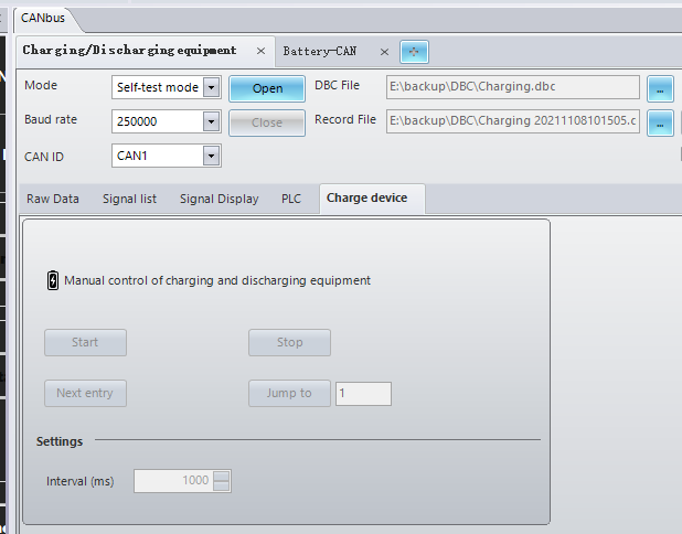
Figure 18. CAN-bus control interface implemented in EDM
The test schedule can be setup to meet the flexible configuration of vibration, charging and discharging equipment, and environmental box control. Preform synchronous control and connect all integrated equipment.

Figure 19. Run schedule in EDM

Figure 20. Send command to environmental chamber software from EDM

Figure 21. Send command to charging/discharging station
The EDM software can send single or multiple Can signals or follow a user-defined schedule.

Figure 22. CAN-bus interface in EDM
After opening the DBC file corresponding to the battery pack, the user can select the CAN signal that needs to be monitored.

Figure 23. CAN measurement signal interface
The CAN signal threshold settings can be configured with low and high alarms, low and high abort, or specific alarm and termination values.

Figure 24. CAN-Bus threshold alarm/abort

Figure 25. CAN-bus signal threshold settings
The CAN signal is displayed in real time. When the warning is triggered, the background color of the corresponding signal will change to yellow, and after the trigger is terminated, the background color of the corresponding signal will change to red.
If the triggers for alarm and abort are set to pause or stop the vibration test, the environmental box and the charging and discharging device can also be synchronized to pause or stop as well.

Figure 26. CAN-bus signal display in EDM
Setting event triggering rules, we can specify CAN warnings and termination operations. For example, the battery pack needs to be automatically charged and discharged during the test. We can set a low warning to perform charging and a high warning to perform discharge. To terminate, you can set a pause or stop the test operation.

Figure 27. Event/Action Rules of EDM
You can choose to save the CAN signal to the local computer, with the default format as CSV. If you choose to record the signal, the CAN signal will be saved to the local computer disk, with the default format as CSV.

Figure 28. CAN bus signals can be saved
The following figure shows the log record of the test stop after the CAN termination is triggered.

Figure 29. Run schedule interface