Engineering teams can utilize finite element analysis (FEA) to simulate mode shapes, resonant frequencies, stiffness, and strength visualizations to help optimize the structural design and minimize costs. The accuracy of the estimated predictions from FEA is dependent on the assumptions made during modeling and analysis and might vary from real-world test data. This article will cover how to set up an FEA frequency study of a simple flat plate fastened at its center.
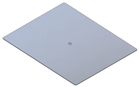
Figure 1. Flat Plate 3D model ready for FEA
An extrusion is used for the main body to model the plate, the corners are chamfered, a fastening through hole is added, and the material is set to aluminum alloy 6061.

Figure 2. Modeling the flat plate using extrusions
To run a frequency study, the following criteria need to be defined:
The boundary condition(s)
The mesh
The boundary condition(s) define how the model would interact in the real-world application. This plate will be fastened using a bolt and washer onto a metal insert.
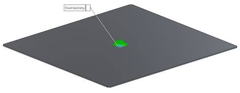
Figure 3. Setting up fixtures in the Frequency Study
The mesh is applied to the model to discretize it. Numerical models are generated based on the type of element used for meshing the model. The finite element method is applied to solve the models to estimate the mode shapes and resonant frequencies of the structure. The resolution of the mesh can be adjusted to improve the accuracy of the numerical model.
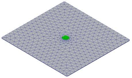
Figure 4. Applying the mesh in the Frequency Study
Once the fixtures and mesh have been set, the frequency study can be run. Shown below are the results of the FEA study used to predict the first 4 mode shapes of the flat plate.


From this analysis, an initial understanding is gained of where the first 4 resonant frequencies could occur as well as what the mode shapes could look like. If the results give the engineering team concerns about how the design will perform, suitable changes can be made to the design before the prototype is built, reducing production time and costs.
Employing finite element analysis as a tool in the design process would help lower costs by reducing hardware prototypes and enhancing design through critical insight into parameters such as material selection for strength and stiffness.
Below are additional examples of frequency studies performed on a variety of fixtures.
100 mm x 150 mm x 10 mm Stainless Steel L Bracket


100 mm x 150 mm x 15 mm Stainless Steel L Bracket


100 mm x 150 mm x 20 mm Stainless Steel L Bracket


Custom L Fixture 725 mm x 600 mm x 550 mm made from plate Aluminum


HER900M Magnesium Round Head Expander


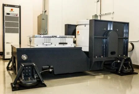
This analysis was performed at Sentek Dynamics’ Charlotte, North Carolina test, demo, service, and assembly facility.
A continuously developing technological field calls for constantly innovating vibration testing systems. Sentek Dynamics is committed to providing powerful and efficient solutions for all your vibration testing needs.
For testing inquires or to schedule a product demo day contact Sentek Dynamics at https://www.sentekdynamics.com/testing-evaluation-services.